Now’s where it starts to get interesting. We’ve got a bunch of 48V batteries that need charged. We’re sitting at 43.8V, after who knows how long between the donor Volt’s death plus 2 and a half months of storage. Do we really have a good battery? I’m going to save the details of how we’re charging the battery for later, and instead focus on some of the battery’s characteristics, and what we’re looking for.
WARNING: Just like a lead-acid battery, there’s a lot of stored energy that can be released from this battery pack. Unlike a lead-acid battery though, this battery pack can release its energy much, much, faster. Extreme care is necessary when exposing the battery terminals. Stray metal shavings, a dropped tool, nut, or bolt could easily result in an explosion from the rapid heating of the shavings, tool, etc.
Before we connect power to the batteries, a check of individual cell voltages is prudent. For each 48V section, there are 12 cell packs (technically, each cell has 3 internal cells, wired in parallel). We’d expect to see 3.65V on each, but more importantly, we want to look for any deviation. This would seem to imply lifting the top plastic cover, as shown, but don’t go there just yet.
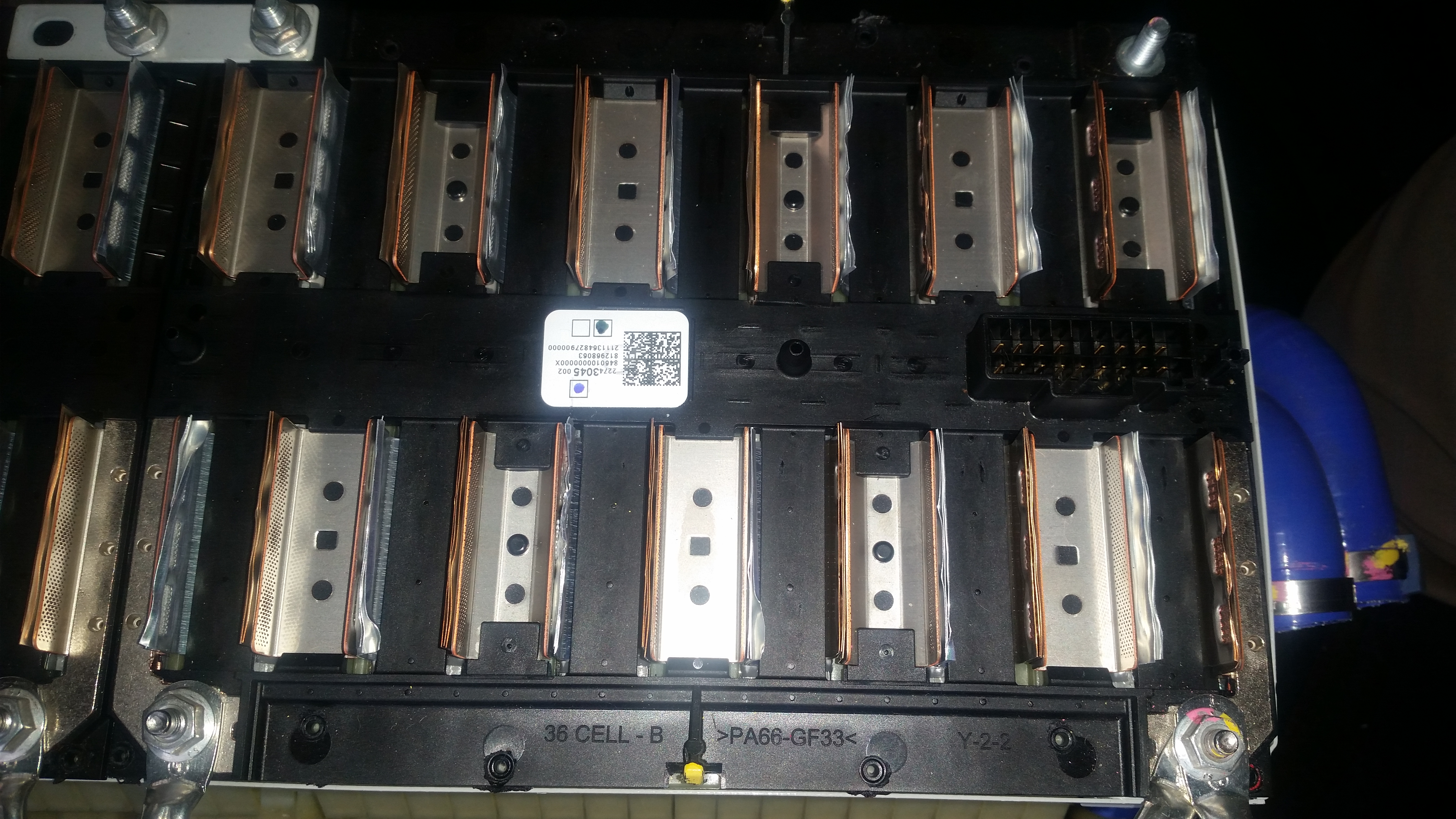
Removing that cover exposes the tabs from each cell pack, and the U-shaped connectors between them. You can also see at the lower left and lower right the 10mm nuts for making the external electrical connections. But in this configuration, it would be all too easy to drop something across the raised tabs, and very likely destroy the pack and severely injure yourself. Fortunately, there’s an easier way to check each of the cells. See the multi-pin connector on the right side? Each terminal on the pack is accessible on that connector, and it’s a far better place to probe with a multi-meter. It can be done with the cover on, minimizing the risk of nastiness.
When we do that on this pack, each cell measures exactly 3.65V, as we’d expect. You can also see that there’s another 48V module physically attached in the picture–I want to charge both at the same time. While the voltages for the two modules measure almost identically, prior to connecting them together I still want to make sure they’re at exactly the same voltage–even slight differences would result in a lot of current flowing between modules. So the first connection is done with a large (9-ohm, 100W rated) resistor in series with the battery leads between packs. Left for a minute or so, this is just extra insurance that there won’t be any surprises when connecting the modules in parallel.
The next step is to get the battery modules connected so that they can be charged, and to collect some data. I’m not going to talk about the charging equipment yet (later, I promise!), but I do want to mention that–particularly on an inverter/charger–there’s going to be a fairly large inrush current to charge various capacitors inside. To prevent sparks, and melting of terminals while hooking things up, I’ve connected the batteries through a disconnect, and used the same resistor from above across the disconnect terminals for a few seconds to charge those capacitors.
We’re going to be charging with a constant-current source. It’s not a “smart” charger in the sense that it knows nothing about this battery pack. It will have to be monitored, and shut off manually. Technically, it’s a regular 3-stage charger, that will be finished before it gets out of the “bulk” phase of charging. I’m going to be monitoring pack voltage constantly, and using a camera to log voltages with time stamps. At several points along the way, I’m also going to be checking individual cell voltages, just to make sure everything operates as expected.
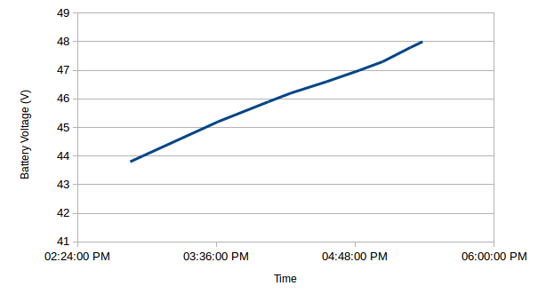
The charging process runs just as expected, and we see in the chart above that there’s a very nice, linear relationship between voltage and time. Since we’re charging at a constant current, we also know that voltage and state of charge are likewise related, with just a little bit of algebra.
With this particular charger and inverter, and sticking within reasonable bounds for battery pack voltages, the inverter would charge this 4kWh (3.2kWh usable) pack in about 5 hours. What’s not recorded is the actual charger output (DC), so we only know state of charge in a relative sense.
So far, everything is going according to plan, and supports the tentative system design. We’ll start to talk about that next time.