Ok, so this project isn’t something for my RV. My parents have a small motorhome, and have occasionally towed a Saturn Vue behind it. There’s a Smart Fortwo in the fleet now, and given that it weighs about half what they’re towing now, it makes sense to get the Smart all set up.
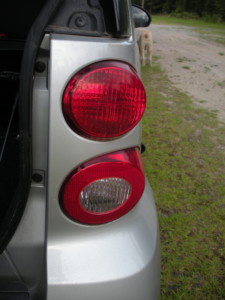
Of course, I’m the resident EE and car guy in the family, and pretty particular about connecting wiring for towing as simply and smartly as possible, which means I get this job to do. Normally the process is pretty simple–find a wiring diagram for the lighting circuits, find the wires for the functions I need, and then figure out the easiest (i.e. closest to the front of the car) place to tie in to them.
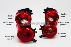
The Fortwo presents a little bit of a challenge though. The best resource for information on this little car is the Evilution site, but the electrical information is for the non-North American version of the car. One of the most prominent differences between the NA version and the rest is the use of combined stop and turn lights here. Now, this makes connection to the motorhome simpler (the standard 7-pin RV plug is a combined stop/turn configuration), but the pin numbers and wire colors don’t match what’s readily available online.
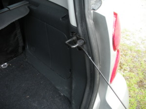
Getting access to the tail lights is easy enough: there’s a plastic access panel on either side of the cargo area, and releasing a clip in the middle frees up the back of the housing where you can see the two bulbs, and–getting a little excited–an empty bulb holder with leads to the plug.
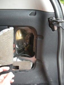
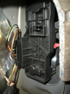
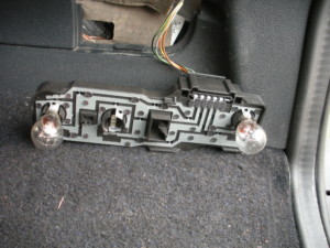
The excitement is killed pretty quickly though, as the lamp and reflector don’t have a hole for the extra bulb.
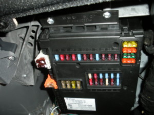
But we can see the wire colors, and then move up to the electrical nerve center of this car–the SAM, or Signal Acquisition Module. It’s basically an I/O board that has a lot of inputs from switches on the car–turn signals, wipers, etc., and miniature relays of various types for controlling outputs. It also incorporates the fuse box, which is visible below and behind the driver’s knee bolster.
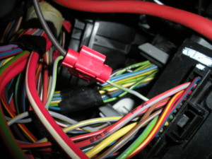
We can remove the SAM and get access to the connectors on the back side by removing the two screws along the front edge. Whether looking at the US or non-US wiring diagrams, the parking lights are the same (though they’re “standing lights” across the pond). They’re a gray wire with a green stripe:
But things get a lot more interesting with the turn signals. When a turn signal is activated on a non-US Smart, with a dedicated bulb in back, the front turn lamp, side repeater, and rear lamp can all be wired together–they’re all on or off under identical logic. But on the US-spec Smart they’re combined with brake lights in the rear–which means they need to be connected to the brake light circuit when braking, but that signal needs to be replaced by the one from the turn signal when turning–i.e. the brake light signal needs to be disconnected from the light where the turn signal is active. Complicating things a bit further is the requirement that those same lights show the brakes (i.e. solid lights) when the hazard flasher is active.
Just about every American car since the dawn of the automotive turn signal has accomplished this logic via a separate set of contacts for the rear lights in the turn signal switch. But not this car. Finding the brake/turn wires at the SAM, I connected power to test that I’d found the right ones. But instead of lighting the rear light, I got the front and side lights. I was just a little confused, and decided to go to the source: factory wiring diagrams at AlldataDIY.
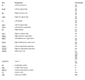
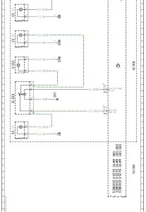
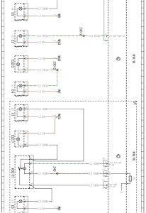
It took a little while to figure out what was going on. There are two relays mounted near the SAM (along the edge toward the front of the car) that both the front and rear lights connect to. When the turn signal switch is active, the relay for that side is energized, connecting the front flashing signal with the rear lamp, and interrupting the stop signal. The control wire for the relay is grounded–the hot side is always powered.
I have to wonder why Smart didn’t just program the logic for the stop lamp–given that the SAM knows about the turn signal switch–to combine the brake/turn logic in software and drive the output for the rear lights accordingly. That would have eliminated two relays and simplified the wiring a good bit. I’m sure there was some good reason…
This configuration means that while front and rear turn signals have the same wire color, they’re only linked together when the turn signal is active. Connect to the correct side of the relay though, and we get almost exactly what we’re after. I was very tempted to use a DPDT relay and the 12V pin from the 7-pin plug to ground the control side of the relays so that the front and side turn signals would operate as well–it would have meant that I could have made all of the connections under the “hood”, but if the auxiliary power pin on the 7-pin connector wasn’t powered, the rear brake/turn lights wouldn’t work–I didn’t like that possibility.
The simplest way to make things work right was to connect the stop/turn wires from the 7-pin plug to the rear stop/turn lights at the relays under the dash. That meant not fishing wire to the rear of the car, but did require getting through the firewall. Can you call it a firewall when the engine is in back?
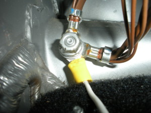
Here are the rest of the connections:
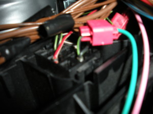
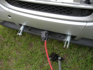
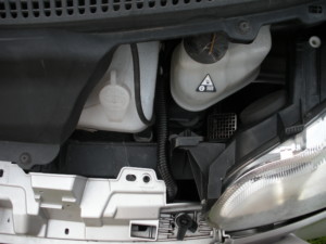
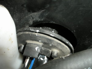
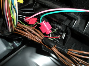
After those connections were made, the plug was tested and everything works as planned.
