And by that, I’m talking about the rest of the old 12V to its final resting place–getting rid of the 6V batteries, and re-purposing the spot they’ll leave behind. Sounds simple enough, doesn’t it?
In principle, yes, but it gets kind of complicated in a hurry:
- The chassis batteries need to be kept on a charger when hooked up to shore power.
- Right now, the generator gets started from the house batteries. Never the right configuration in my mind, as one of the main reasons for starting the generator is because the house batteries need charged. Going forward, the chassis batteries will need to start the generator.
- The battery separator won’t be needed any more, at least not as it’s configured now.
- A new 12V power supply will be needed to keep the lights on, run the water pump, slide-out, and run a few other things. I suspect that some of them will be replaced with time, maybe even doing away with 12V stuff altogether.
I guess that still doesn’t sound too complicated, until you start looking at the wiring (going from front to back along driver’s side of rig):
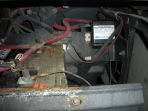
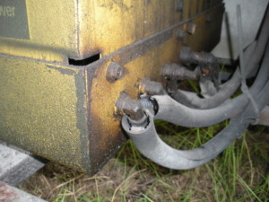
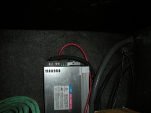
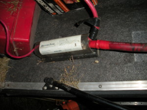
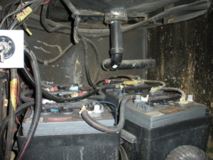
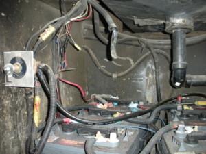
Of course, deciphering what’s here is the first challenge. If we start at the battery separator, it’s pretty easy to follow the leads to figure out that the left terminal goes to the chassis batteries, and the right side goes to the house system. From there it gets a little murky, but I ended up using the DC ammeter from last time to figure some of it out.
How’s that work? Well, right now I’m hooked up to shore power. The charger is working, the separator contacts are closed and feeding both battery banks, and there are a variety of lights and things turned on inside. Current flows to power all of them. I first start by measuring power out of the charger, which shows about 12A. Back at the chassis batteries, I measure 1.5A (which is the “float” charge going to them). That leaves 10.5A between the house batteries and what’s on inside.
Measuring at the batteries, I was able to figure out which wire was connected to the house distribution panel, and which one was coming from the charger. On the multimeter, there’s a + sign on the top of the clamp–with that facing up and a positive reading on the meter, current is flowing up through the clamp. If it’s a negative reading, it’s flowing down.
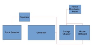
Here’s a diagram showing what it looks like now (positive side only):
With any luck, it’ll end up a little bit cleaner when done.
The first step is to turn off the main disconnect for the house battery system. But that only disconnects the ground side of the circuit, and there would appear to be some things that are directly grounded to the batteries and/or chassis. It also doesn’t disconnect the link between the house battery and chassis battery positive terminals via the battery separator, so the power leads are still connected to 12V, and the chassis is still grounded. (More on battery connections and the order of operations that apply generally in another post.)
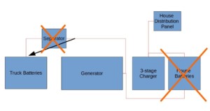
So in order to render the various leads in the house battery compartment safe to disconnect, we also need to disconnect the battery separator. Since the battery separator and the chassis batteries are next to each other with a short (foot-long) cable, I’ll remove that cable entirely.
Next operation is disconnecting the batteries. There are a number of power and ground connections–to the charger, house distribution panel, generator, inverter, etc. that need to be disconnected from the batteries. There are also 3 links between the series strings of batteries, making for a total of 12 battery terminals to disconnect. The batteries are then hauled out and taken to a recycler, where they’re worth about $85.
Here’s what the diagram looks like now:
At this point, the dead weight is out, but none of the house 12V systems work. Since that includes lights, the water pump, and controls for the air conditioning, that’s a problem to be addressed ASAP, but writing it up will have to wait until next time.
EEK! All Greek to me.