Here’s the answer to an electrical question nobody’s asking: How do I operate a 3-way circuit without a three way switch? Why would I want to do that?
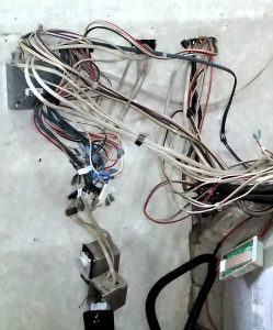
As part of a kitchen remodel, I was wanting to clean up the mess of switches around the end of the kitchen cabinets. Right by the entry door, there were 15 switches of various types–some of the 3-way RV variety, some residential-style, awning controls that uses Carling switches, another type for the water heater, and still another for the holding tank heaters. It wasn’t particularly attractive–ome had black mounting panels, others white, and they were different sizes and shapes. A number of switches controlled outside lights, where you couldn’t really see whether it was on or off–including a motion-activated porch light that’s usually off even when the switch is on.
That last one is what made me want to use switches with indicator lights. I also liked the idea for the three-way switches, to make it easier to find the right switch to turn off a light.
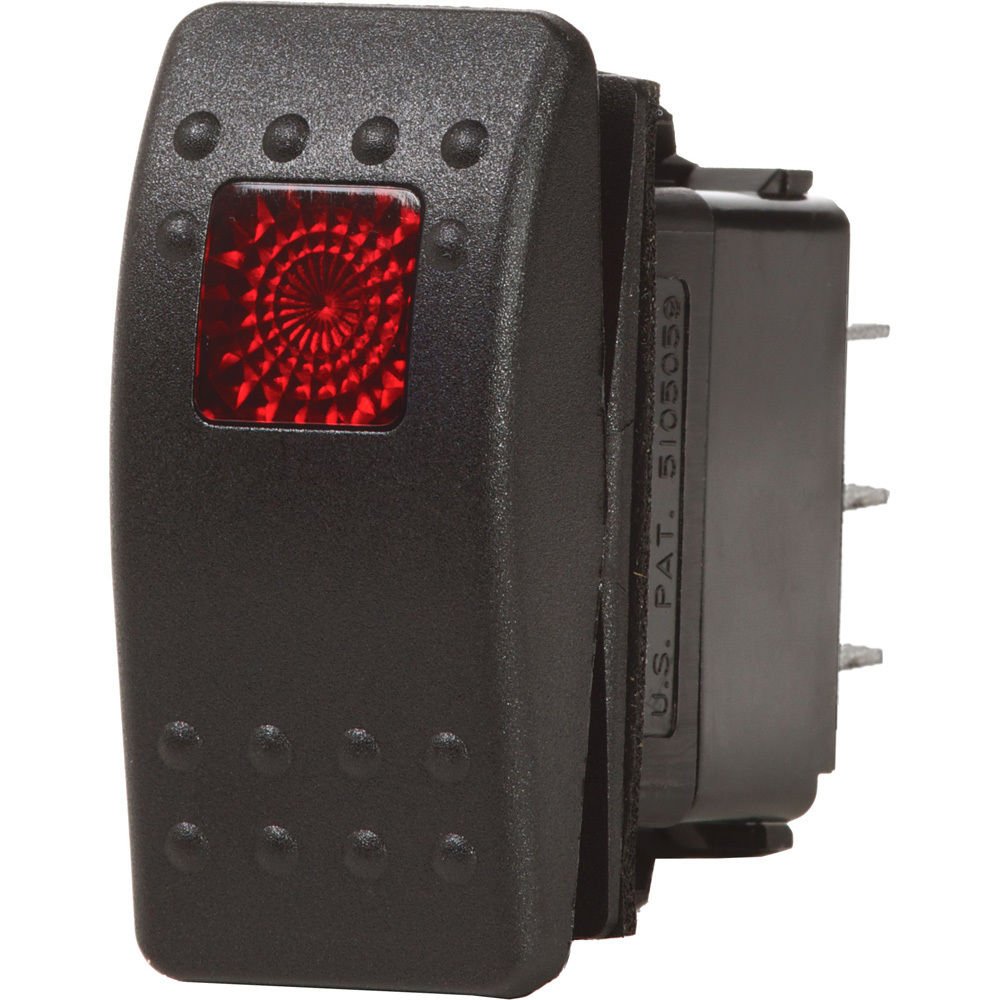
After a fairly lengthy search for what I thought surely already existed, I came up empty trying to find a switch that fit the bill. I wanted high-quality, single-pole double-throw (SPDT or 3-way) switches with an indicator light. The closest I was able to get was a switch from Carling. They manufacture a wide variety of switches, mostly for the automotive and marine industries. Depending on the vendor, they’re sometimes sold as complete switches, other places sell the actuator and switch body separately. And while you can use spade connectors with them directly, I made use of their connectors so that I could easily unplug a switch without worrying about which wire goes where. I bought on/off rocker switches with illumination, and Contura II actuators. Not cheap at around $15 each, but I’ve used them before, and they’re a very high quality switch.

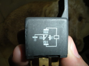
So how do we make a 3-way switch out of these? Relays. A standard Bosch-style 5-pin automotive relay is a 3-way (or SPDT) switch, just electrically operated. Pins 30 (common), 87 (normally open), and 87a (normally closed) are the switching contacts, and pins 85 and 86 are for the coil that operates them.
With our rocker switch turned off, there’s no power to the relay coil and pins 30 and 87a are connected as shown in the diagram above. When we supply power to the coil (our rocker switch turned on), the connection with 87a is opened, and pins 30 and 87 are connected.
We’ll configure the rocker switch to control the relay, and show how to wire it all up in part 2, just as soon as I get my wiring diagrams presentable.


One Comment Add yours