Last time, we talked rather abstractly about why a space heater doesn’t draw more power when supply voltage drops. This time, we’re going to talk about it with a real space heater, current and voltage measurements, and a short, poorly produced video (I made it, so I can say so). More pictures and fewer formulas this time!
Equipment
- Ordinary 1500W space heater. Mine is several years old, here’s something similar.
- Transformer and switch box. This will get its own post soon, but it’s a circuit that can drop supply voltage by 10%.
- Multimeter. I’ve already written about them in general, and the one I’m using in this post.
- Line splitter, from this post, will let me use the clamp-on ammeter function of my multimeter to measure current.
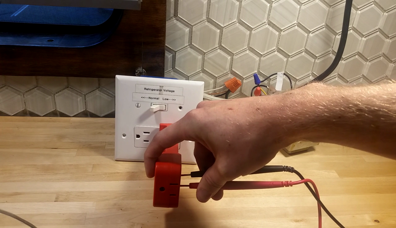
First Measurements
The first thing we’ll do is measure voltage, and see that the switching circuit works as intended. The voltmeter is set to measure AC volts, with the line splitter plugged in to the receptacle. On the end of the line splitter, there are two small holes for the meter’s leads–which is a much easier and safer place to measure voltage than by sticking the probes directly into the receptacle. One lead in each and we’ll see about 120V on the meter:

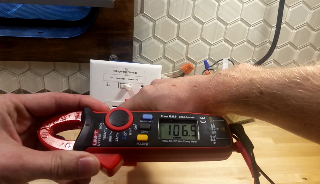
If we flip the switch, bringing the transformer into the picture and subtracting about 10%, we expect to see voltage between 105V and 110V:
Next step is plugging the space heater into the line splitter. If we turn on the fan and flip the switch, you’ll hear the sound chance (video at the end of this post). The motor is slowing down with the reduced supply voltage. This is not a synchronous induction motor, like we have in our air conditioning compressors, but a fractional-horsepower universal motor–it’s basically a DC motor, where speed is a function of input voltage and load.
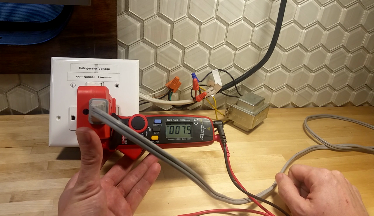
Turning on the heat, let’s see how current changes. With the switch set to pass through supply voltage, we measure 7.5 amps:
If we wanted to measure current on something not drawing so much power, or wanted a more accurate measurement, we can use the 10X loop on the line splitter–what this does is run the power lead through the loop 10 times the same direction, making the current sensed appear 10 times larger. Doing this, we essentially get another significant digit from our meter:
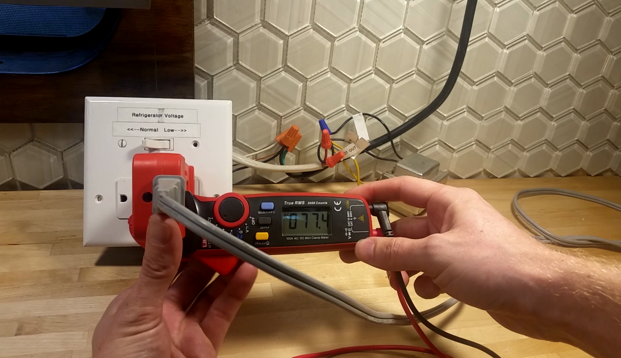
Now we’ll flip the switch, dropping the supply voltage, and measure current again:

Now the Math. Does it Make Sense?
Now for just a little bit of algebra to see if those numbers make sense. Recall Ohm’s Law:
\(V=IR\)We’ll add subscripts to tell the two pieces of information apart, and rearrange solving for R. First just with the subscripts:
\(V_1=I_1 R\) \(V_2=I_2 R\)Solved for R:
\(R=\frac{V_1}{I_1}\) \(R=\frac{V_2}{I_2}\)Let’s plug in some numbers, and see how close those come out:
\(R=\frac{V_1}{I_1}=\frac{120.7V}{7.5A}=16.1 \Omega\) \(R=\frac{V_2}{I_2}=\frac{106.5V}{6.8A}=15.7 \Omega\)The numbers are a little different, but within 3%. There is a slight temperature effect on resistance, which will account for most of that difference, but for now we can say that resistance is approximately fixed. In that case, we can rewrite the two equations above as a single relationship, and ignore what R actually is:
\(\frac{V_1}{I_1}=\frac{V_2}{I_2}\)With that relationship, we can estimate what current will be drawn for a hypothetical supply voltage as long as we have a supply voltage and current measurement. But perhaps more interesting is to look at power. We know that power, P, is current, I, times voltage, V. So we know that with normal supply voltage
\(P=IV=(7.5A)(120.7V)=905VA\approx905W\)With the reduced supply voltage,
\(P=IV=(6.8A)(106.5V)=724VA\approx724W\)The difference is a lot more obvious with these numbers. That’s a result of the quadratic nature of voltage with a resistive load. Recalling the equations from last time, relating power to either current and voltage or voltage and resistance, we should get about the same result:
\(P=IV=\frac{V^2}{R}\) \(P=\frac{V^2}{R}=\frac{(120.7V)^2}{16\Omega}=911W\) \(P=\frac{V^2}{R}=\frac{(106.5V)^2}{16\Omega}=709W\)It’s basically the same math, but it’s a little easier to see the effect of voltage on power both directly and as it affects the current flowing. I’ll save it for later, but that’s also a big part of why your lights quickly get dim as voltage falls.
Here’s the video:
https://rvnerds.com/wp-content/uploads/2017/02/Heater.mp4